一、实验目的
掌握一般性计数器的VHDL设计方法,熟悉程序文本和原理图结合方法设计电路。掌握CASE语句的基本使用方法。
二、实验内容
首先用VHDL语言设计10进制计数器,要求电路具有复位端和使能端,仿真验证其正确性,并将其封装成一个元件;
用两个10进制计数器扩展成一个100进制计数器,注意两个10进制计数器间管脚的连接方式,画出其原理图并用QUARTUSⅡ软件仿真验证,仿真验证所设计电路的功能;
首先用CASE语句设计7段显示译码器电路,仿真验证其正确性,并将其封装成一个元件;用7段显示译码器将100进制计数器的两组4位二进制输出转换为10进制显示,画出其原理图并用QUARTUSⅡ软件仿真验证.
三、实验设计
1.首先用VHDL语言设计一个10进制计数器,该计数器具有复位端和使能端,因此需要使用条件语句实现其功能,并且应该是四位的输入输出。VHDL代码如下:
Library ieee;
Use ieee.Std_Logic_1164.All;
Use ieee.Std_Logic_Unsigned.All;
Entity count10 is
  port(clk,rst,en,load: in Std_Logic;
      data: in Std_Logic_Vector (3 downto 0);
      dout: out Std_Logic_Vector (3 downto 0);
      cout: out Std_Logic);
End Entity count10;
Architecture bhv of count10 is
begin
  process (clk,rst,en,load)
  variable q: Std_Logic_Vector (3 downto 0);
  begin
    if rst='0' then q:=(others=>'0');
    elsif clk 'event and clk='1' then
    if en='1' then
      if (load='0') then q:=data; else
      if q<9 then q:=q+1;
      else q:=(others=>'0');
      end if;
      end if;
    end if;
    end if;
    if q="1001" then cout<='1';
    else cout<='0';
    end if;
    dout<=q;
  End process;
End Architecture bhv;
验证其正确性,仿真波形图如下:
2. 用两个10进制计数器扩展成一个100进制计数器,注意其引脚的连接方式。
仿真验证其正确性,波形图如下:
3. 用CASE语句设计7段显示译码器电路,根据不同数字对应显示不同数码管的情况,设计正确的对应关系。VHDL代码如下:
LIBRARY IEEE;
USE IEEE.STD_LOGIC_1164.ALL ;
use Ieee.std_logic_unsigned.all;
entity led7 is
  port (indata: in std_logic_vector(3 downto 0);
    odata: out std_logic_vector(6 downto 0));
end entity led7;
architecture bhv of led7 is
  begin
  process (indata)
  begin
  case (indata) is
    when "0000" => odata<= "0111111" ;
    when "0001" => odata<= "0001110" ;
    when "0010" => odata<= "1011011" ;
    when "0011" => odata<= "1001111" ;
    when "0100" => odata<= "1100110" ;
    when "0101" => odata<= "1101101" ;
    when "0110" => odata<= "1111101" ;
    when "0111" => odata<= "0000111" ;
    when "1000" => odata<= "1111111" ;
    when "1001" => odata<= "1101111" ;
    when others => null;
  end case;
  end process;
end architecture bhv;
将其封装成一个元件。在VHDL描述页面,选file→create/update→create symbol files for current file,把编写的代码封装成一个元件。
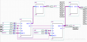
用7段显示译码器将100进制计数器的两组4位二进制输出转换为10进制显示。原理图如下:
验证其正确性,仿真波形如下:


