1. 实验设想
现有总部公司晓飞网络科技公司,在济南设立。如今在烟台、青岛两地开设分公司,有业务需求:烟台与青岛两地分公司仍需通信,但为了安全性,流量需要经过济南总公司,并且通过运营商网络MPLS VPN 实现通信所有通信。
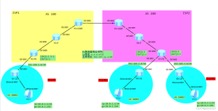
2. 拓扑设计

根据设想,我们可以理解:分公司去往另一个分公司的路由,要从总公司那里获得。
所以可以在 PE1设备上创建两个实例,一个收方向实例(in),一个是出方向实例(out),PE1的两个实例分别通过 OSPF与总公司的 OSPF 建立邻接关系,交互 LSA,生成路由。
收方向的实例用来接收 PE2 和 PE3 发来的各分公司的路由,发给总公司 CE设备,再由总公司的 CE 设备通过 OSPF 把路由发给 PE1 的出方向实例路由表中,然后再由 MP-BGP 传递给 PE2 和PE3 设备,完成所有的路由交互。
3. 配置脚本
PE1 配置
ipvpn-instanceinipv4-familyroute-distinguisher1:2vpn-target25:2536:36import-extcommunity//入方向实例ipvpn-instanceoutipv4-familyroute-distinguisher2:1vpn-target52:5263:63export-extcommunity//出方向实例mplslsr-id1.1.1.1mplsmplsldp#isis1is-levellevel-2cost-stylewidenetwork-entity49.0000.0000.0000.0001.00#interfaceGigabitEthernet0/0/0ipaddress12.1.1.1255.255.255.0isisenable1mplsmplsldp#interfaceGigabitEthernet0/0/1ipaddress13.1.1.1255.255.255.0isisenable1mplsmplsldp#interfaceGigabitEthernet0/0/2.14dot1qterminationvid14ipbindingvpn-instanceinipaddress192.168.14.1255.255.255.0ospfenable14area0.0.0.0arpbroadcastenableinterfaceGigabitEthernet0/0/2.41dot1qterminationvid41ipbindingvpn-instanceoutipaddress192.168.41.1255.255.255.0ospfenable41area0.0.0.0arpbroadcastenableinterfaceLoopBack0ipaddress1.1.1.1255.255.255.255isisenable1#bgp123peer2.2.2.2as-number123peer2.2.2.2connect-interfaceLoopBack0peer3.3.3.3as-number123peer3.3.3.3connect-interfaceLoopBack0#ipv4-familyunicastundosynchronizationpeer2.2.2.2enablepeer3.3.3.3enable#ipv4-familyvpnv4policyvpn-targetpeer2.2.2.2enablepeer3.3.3.3enable//使能传递VPNv4 路由 #ipv4-familyvpn-instanceoutimport-routeospf41ospf14router-id14.1.1.1vpn-instanceinimport-routebgpdn-bit-setdisablesummaryarea0.0.0.0ospf41router-id41.1.1.1vpn-instanceoutarea0.0.0.0#
PE2 配置
ipvpn-instancevpn2ipv4-familyroute-distinguisher2:2vpn-target25:25export-extcommunityvpn-target52:52import-extcommunitymplslsr-id2.2.2.2mplsmplsldp#isis1is-levellevel-2cost-stylewidenetwork-entity49.0000.0000.0000.0002.00#interfaceGigabitEthernet0/0/0ipaddress12.1.1.2255.255.255.0isisenable1mplsmplsldp#interfaceGigabitEthernet0/0/1ipbindingvpn-instancevpn2ipaddress25.1.1.2255.255.255.0ospfenable1area0.0.0.0#interfaceLoopBack0ipaddress2.2.2.2255.255.255.255isisenable1#bgp123peer1.1.1.1as-number123peer1.1.1.1connect-interfaceLoopBack0peer3.3.3.3as-number123peer3.3.3.3connect-interfaceLoopBack0#ipv4-familyunicastundosynchronizationpeer1.1.1.1enablepeer3.3.3.3enable#ipv4-familyvpnv4policyvpn-targetpeer1.1.1.1enablepeer3.3.3.3enable#ipv4-familyvpn-instancevpn2import-routeospf1ospf1router-id2.2.2.2vpn-instancevpn2import-routebgparea0.0.0.0#
PE3 配置
ipvpn-instancevpn3ipv4-familyroute-distinguisher3:3vpn-target36:36export-extcommunityvpn-target63:63import-extcommunitymplslsr-id3.3.3.3mplsmplsldp#isis1is-levellevel-2cost-stylewidenetwork-entity49.0000.0000.0000.0003.00#interfaceGigabitEthernet0/0/0ipbindingvpn-instancevpn3ipaddress36.1.1.3255.255.255.0ospfenable1area0.0.0.0#interfaceGigabitEthernet0/0/1ipaddress13.1.1.3255.255.255.0isisenable1mplsmplsldp#interfaceLoopBack0ipaddress3.3.3.3255.255.255.255isisenable1bgp123peer1.1.1.1as-number123peer1.1.1.1connect-interfaceLoopBack0peer2.2.2.2as-number123peer2.2.2.2connect-interfaceLoopBack0#ipv4-familyunicastundosynchronizationpeer1.1.1.1enablepeer2.2.2.2enable#ipv4-familyvpnv4policyvpn-targetpeer1.1.1.1enablepeer2.2.2.2enable#ipv4-familyvpn-instancevpn3import-routeospf1ospf1router-id3.3.3.3vpn-instancevpn3import-routebgparea0.0.0.0
PE4 配置
interfaceGigabitEthernet0/0/2.14dot1qterminationvid14ipaddress192.168.14.4255.255.255.0ospfenable1area0.0.0.0arpbroadcastenableinterfaceGigabitEthernet0/0/2.41dot1qterminationvid41ipaddress192.168.41.4255.255.255.0ospfenable1area0.0.0.0arpbroadcastenableinterfaceLoopBack0ipaddress4.4.4.4255.255.255.255ospfenable1area0.0.0.0#ospf1router-id4.4.4.4area0.0.0.0
PE5 配置
interfaceGigabitEthernet0/0/1ipaddress25.1.1.5255.255.255.0ospfenable1area0.0.0.0#interfaceLoopBack0ipaddress5.5.5.5255.255.255.255ospfenable1area0.0.0.0#ospf1router-id5.5.5.5area0.0.0.0
PE6 配置
interfaceGigabitEthernet0/0/0ipaddress36.1.1.6255.255.255.0ospfenable1area0.0.0.0#interfaceLoopBack0ipaddress6.6.6.6255.255.255.255ospfenable1area0.0.0.0#ospf1router-id6.6.6.6area0.0.0.0
4. 总结
配置完成之后,我们可以测试,在烟台分公司 CE设备上使用 tracert命令追踪到
青岛分公司 CE 设备上的路径:

由此图可以看出,路径为 PE2-PE1-PE4-PE1-PE3-青岛分公司 CE,是符合我们的流量设计的

配置思路:
PE2 的RT 值为:出方向 25:25,入方向 52:52
PE3 的RT 值为:出方向 36:36,入方向 63:63;
PE1 的RT 值为:入方向实例中:入方向 25:25 36:36
出方向实例中:出方向:63:6352:52
根据RT 值来看,PE2 和PE3 发送的 VPNv4 路由,会被PE1 的入方向实例中接收,而不被发送出去。然后使用 OSPF 发送给济南总公司 CE 设备上,再由济南总公司 CE 设备上发送给 PE1,此时 PE1 的出方向实例中就会有了烟台、青岛分公司 CE 设备的路由。再由PE1 的出方向实例发送出去,根据RT 值来看,PE2 和 PE3 会接收到该路由。
注:PE设备上需要执行双点双向的引入。