Eth-trunk : LACP模式链路聚合实战
需求描述
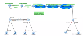
PC1和PC3数据vlan10 ,网段为192.168.10.0 /24
PC2和PC4数据vlan20 ,网段为192.168.20.0 /24
确保设备之间互联互通,使用最大互联带宽并没有环路
确保相同网段的PC可以互通
判断交换机之间的每个端口的角色和状态
拓扑图

配置思路
配置终端设备
配置PC机的IP地址参数
配置网络设备
先初始化
创建vlan
将接口加入vlan并设置端口模式access
eth-trunk
创建eth-trunk的端口
设置eth-trunk模式
添加接口成员
设备端口trunk并允许所有vlan通过
配置命令
二层交换机配置 s3 s4 s5 s6
s3
1.S3交换机的初始配置<Huawei>utm\\关闭信息干扰<Huawei>system-view\\进入系统视图    [Huawei]sysnameS3\\设置交换机的名字为S32.S3创建vlan1020    [S3]vlanbatch1020\\创建vlan10203.S3将e0/0/1加入vlan10并设置链路是access链路    [S3]inte0/0/1   [\\进入接口0/0](file:///\\\\进入接口0/0)/1    [S3-Ethernet0/0/1]portlink-typeaccess\\设置链路为接入链路(access链路)    [S3-Ethernet0/0/1]portdefaultvlan10   [\\将接口加入vlan10](\\\\将接口加入vlan10)
4.创建链路聚合接口eth-trunk1并将设置模式为lacp、加入成员并设置链路为tunk并允许所有vlan通过    [S3]interfaceEth-Trunk1\\[创建链路聚合的端口1](file:///\\\\创建链路聚合的端口1)    [S3-Eth-Trunk1]modelacp-static\\设置链路为动态lacp    [S3-Eth-Trunk1]trunkporte0/0/3\\将接口加入到负载模式    [S3-Eth-Trunk1]trunkporte0/0/4     [\\将接口加入到负载模式](file:///\\\\将接口加入到负载模式)    [S3-Eth-Trunk1]portlink-typetrunk\\设置为trunk链路    [S3-Eth-Trunk1] porttrunkallow-passvlanall\\并允许所有vlan通过    [S3-Eth-Trunk1]displayeth-trunk1\\查看eth-trunk
s4
1.S4交换机的初始配置<Huawei>utm\\关闭信息干扰<Huawei>system-view\\进入系统视图 [Huawei]sysnameS4\\设置交换机的名字为S42.S4创建vlan1020 [S4]vlanbatch1020\\创建vlan10203.S4将e0/0/1加入vlan10并设置链路是access链路 [S4]inte0/0/1 [\\进入接口0/0](file:///\\\\进入接口0/0)/1 [S4-Ethernet0/0/1]portlink-typeaccess\\设置链路为接入链路(access链路) [S4-Ethernet0/0/1]portdefaultvlan20\\将接口加入vlan204.创建链路聚合接口eth-trunk1并将设置模式为lacp、加入成员并设置链路为tunk并允许所有vlan通过 [S4]interfaceEth-Trunk2\\[创建链路聚合的端口2](file:///\\\\创建链路聚合的端口1) [S4-Eth-Trunk2]modelacp-static\\设置链路为动态lacp [S4-Eth-Trunk2]trunkporte0/0/5\\将接口加入到负载模式 [S4-Eth-Trunk2]trunkporte0/0/6 [\\将接口加入到负载模式](file:///\\\\将接口加入到负载模式) [S4-Eth-Trunk2]portlink-typetrunk\\设置为trunk链路 [S4-Eth-Trunk2] porttrunkallow-passvlanall\\并允许所有vlan通过 [S4-Eth-Trunk2]displayeth-trunk1\\查看eth-trunk
s5
1.S5交换机的初始配置<Huawei>utm\\关闭信息干扰<Huawei>system-view\\进入系统视图    [Huawei]sysnameS5\\设置交换机的名字为S52.S5创建vlan1020    [S5]vlanbatch1020\\创建vlan10203.S5将e0/0/1加入vlan10并设置链路是access链路    [S5]inte0/0/1   [\\进入接口0/0](file:///\\\\进入接口0/0)/1    [S5-Ethernet0/0/1]portlink-typeaccess\\设置链路为接入链路(access链路)    [S5-Ethernet0/0/1]portdefaultvlan10   [\\将接口加入vlan10](\\\\将接口加入vlan10)
4.创建链路聚合接口eth-trunk1并将设置模式为lacp、加入成员并设置链路为tunk并允许所有vlan通过    [S5]interfaceEth-Trunk1\\[创建链路聚合的端口1](file:///\\\\创建链路聚合的端口1)    [S5-Eth-Trunk1]modelacp-static\\设置链路为动态lacp    [S5-Eth-Trunk1]trunkporte0/0/3\\将接口加入到负载模式    [S5-Eth-Trunk1]trunkporte0/0/4     [\\将接口加入到负载模式](file:///\\\\将接口加入到负载模式)    [S5-Eth-Trunk1]portlink-typetrunk\\设置为trunk链路    [S5-Eth-Trunk1] porttrunkallow-passvlanall\\并允许所有vlan通过    [S5-Eth-Trunk1]displayeth-trunk1\\查看eth-trunk
s6
1.S6交换机的初始配置<Huawei>utm\\关闭信息干扰<Huawei>system-view\\进入系统视图 [Huawei]sysnameS6\\设置交换机的名字为S62.S6创建vlan1020 [S6]vlanbatch1020\\创建vlan10203.S6将e0/0/1加入vlan10并设置链路是access链路 [S6]inte0/0/1 [\\进入接口0/0](file:///\\\\进入接口0/0)/1 [S6-Ethernet0/0/1]portlink-typeaccess\\设置链路为接入链路(access链路) [S6-Ethernet0/0/1]portdefaultvlan20\\将接口加入vlan204.创建链路聚合接口eth-trunk1并将设置模式为lacp、加入成员并设置链路为tunk并允许所有vlan通过 [S6]interfaceEth-Trunk2\\[创建链路聚合的端口2](file:///\\\\创建链路聚合的端口1) [S6-Eth-Trunk2]modelacp-static\\设置链路为动态lacp [S6-Eth-Trunk2]trunkporte0/0/5\\将接口加入到负载模式 [S6-Eth-Trunk2]trunkporte0/0/6 [\\将接口加入到负载模式](file:///\\\\将接口加入到负载模式) [S6-Eth-Trunk2]portlink-typetrunk\\设置为trunk链路 [S6-Eth-Trunk2] porttrunkallow-passvlanall\\并允许所有vlan通过 [S6-Eth-Trunk2]displayeth-trunk1\\查看eth-trunk
三层交换机配置 s1 s2
s1
S1交换机的初始配置<Huawei>utm\\关闭信息干扰<Huawei>system-view\\进入系统视图 [Huawei]sysnameS1\\设置交换机的名字为S1S1创建vlan1020 [S1]vlanbatch1020\\创建vlan10203.创建链路聚合接口eth-trunk1、2并将设置模式为lacp、加入成员并设置链路为tunk并允许所有vlan通过 [S1]interfaceEth-Trunk1\\[创建链路聚合的端口1](file:///\\\\创建链路聚合的端口1) [S1-Eth-Trunk1]modelacp-static\\设置链路为动态lacp [S1-Eth-Trunk1]trunkportg0/0/3\\将接口加入到负载模式 [S1-Eth-Trunk1]trunkportg0/0/4 [\\将接口加入到负载模式](file:///\\\\将接口加入到负载模式) [S1-Eth-Trunk1]portlink-typetrunk\\设置为trunk链路 [S1-Eth-Trunk1] porttrunkallow-passvlanall\\并允许所有vlan通过 [S1]interfaceEth-Trunk2\\[创建链路聚合的端口2](file:///\\\\创建链路聚合的端口1) [S1-Eth-Trunk2]modelacp-static\\设置链路为动态lacp [S1-Eth-Trunk2]trunkportg0/0/5\\将接口加入到负载模式 [S1-Eth-Trunk2]trunkportg0/0/6 [\\将接口加入到负载模式](file:///\\\\将接口加入到负载模式) [S1-Eth-Trunk2]portlink-typetrunk\\设置为trunk链路 [S1-Eth-Trunk2] porttrunkallow-passvlanall\\并允许所有vlan通过 [S1]interfaceEth-Trunk3\\[创建链路聚合的端口3](file:///\\\\创建链路聚合的端口1) [S1-Eth-Trunk3]modelacp-static\\设置链路为动态lacp [S1-Eth-Trunk3]trunkportg0/0/7\\将接口加入到负载模式 [S1-Eth-Trunk3]trunkportg0/0/8 [S1-Eth-Trunk3]trunkportg0/0/9 [S1-Eth-Trunk3]portlink-typetrunk\\设置为trunk链路 [S1-Eth-Trunk3] porttrunkallow-passvlanall\\并允许所有vlan通过 [S1]displayeth-trunk1\\查看eth-trunk [S1]displayeth-trunk2\\查看eth-trunk [S1]displayeth-trunk3\\查看eth-trunk
[S1]display eth-trunk 1 \查看 eth-trunk

[S1]display eth-trunk 2 \查看 eth-trunk

s2
<Huawei>utm\\关闭信息干扰<Huawei>system-view\\进入系统视图[Huawei]sysnameS2\\设置交换机的名字为S2S2创建vlan1020[S2]vlanbatch1020\\创建vlan1020创建链路聚合接口eth-trunk1、2并将设置模式为lacp、加入成员并设置链路为tunk并允许所有vlan通过  [S2]interfaceEth-Trunk1\\[创建链路聚合的端口1](file:///\\\\创建链路聚合的端口1)  [S2-Eth-Trunk1]modelacp-static\\设置链路为动态lacp  [S2-Eth-Trunk1]trunkportg0/0/3\\将接口加入到负载模式  [S2-Eth-Trunk1]trunkportg0/0/4     [\\将接口加入到负载模式](file:///\\\\将接口加入到负载模式)  [S2-Eth-Trunk1]portlink-typetrunk\\设置为trunk链路  [S2-Eth-Trunk1] porttrunkallow-passvlanall\\并允许所有vlan通过  [S2-Eth-Trunk1]displayeth-trunk1\\查看eth-trunk  [S2]interfaceEth-Trunk2\\[创建链路聚合的端口2](file:///\\\\创建链路聚合的端口1)  [S2-Eth-Trunk2]modelacp-static\\设置链路为动态lacp  [S2-Eth-Trunk2]trunkportg0/0/5\\将接口加入到负载模式  [S2-Eth-Trunk2]trunkportg0/0/6     [\\将接口加入到负载模式](file:///\\\\将接口加入到负载模式)  [S2-Eth-Trunk2]portlink-typetrunk\\设置为trunk链路  [S2-Eth-Trunk2] porttrunkallow-passvlanall  [\\并允许所有vlan通过](\\\\并允许所有vlan通过)
  [S2-Eth-Trunk2]displayeth-trunk2\\查看eth-trunk  [S2]interfaceEth-Trunk3\\[创建链路聚合的端口3](file:///\\\\创建链路聚合的端口1)  [S2-Eth-Trunk3]modelacp-static\\设置链路为动态lacp  [S2-Eth-Trunk3]trunkportg0/0/7\\将接口加入到负载模式  [S2-Eth-Trunk3]trunkportg0/0/8  [S1-Eth-Trunk3]trunkportg0/0/9  [S2-Eth-Trunk3]portlink-typetrunk\\设置为trunk链路  [S2-Eth-Trunk3] porttrunkallow-passvlanall\\并允许所有vlan通过  [S2-Eth-Trunk3]displayeth-trunk3\\查看eth-trunk
[S2-Eth-Trunk2]display eth-trunk 2 \查看 eth-trunk

[S2-Eth-Trunk3]display eth-trunk 3 \查看 eth-trunk
设置最大 链路数,及开启抢占功能
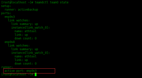
Local:本地信息 Partner:对端信息
Svstem Prioritv:32768 系统的优先级
System ID:4clf-cc4e-5 系统的mac地址
MAX Active-linknumber:8 最大的活动链路数是8条
链路数是可以进行调整的我们可以调整为2条
Number of Up Port In Trunk:0 目前有几条
S2设置他的链路为2:[S2]displayeth-trunk1\\查看eth-trunk[S2]inteth-trunk1\\进入eth-trunk1[S2-Eth-Trunk1]maxactive-linknumber2 [\\设置为2](file:///\\\\设置为2)条链路修改sw2为主设备,默认值是32768我们可以设置为100[S2]lacppriority100\\设置默认值为100[S2]displayeth-trunk1\\查看eth-trunk配置启用抢占模式S1S2都需要开启[S2]displayeth-trunk3\\查看eth-trunk[S2-Eth-Trunk1]lacppreemptenable [\\配置抢占模式](file:///\\\\配置抢占模式)[S1]displayeth-trunk3\\查看eth-trunk[S1-Eth-Trunk1]lacppreemptenable [\\配置抢占模式](file:///\\\\配置抢占模式)PreemptDelayTime:30当前抢占功能已开启30秒后抢
[S2]display eth-trunk \查看 eth-trunk


总结:
1、进入eth-trunk视图interfaceeth-trunk1设置模式modelacp-static添加链路trunkportg0/0/1设置端口模式portlink-typetrunkporttrunkallow-passvlanall设置最大链路数max-active-linknumber2开启抢占模式lacppreemptenable设置主设备的优先级默认值是32768我们可以设置为100 [S2]lacppriority100