引言
由于本文内容跟小编前期更新的“浅析pcie”系列文章有关,建议阅读本文之前,请先参考阅读,如果觉得不需要,可以略过;
在pcie协议中,关于TLP数据传输过程,有两个比较重要的参数:
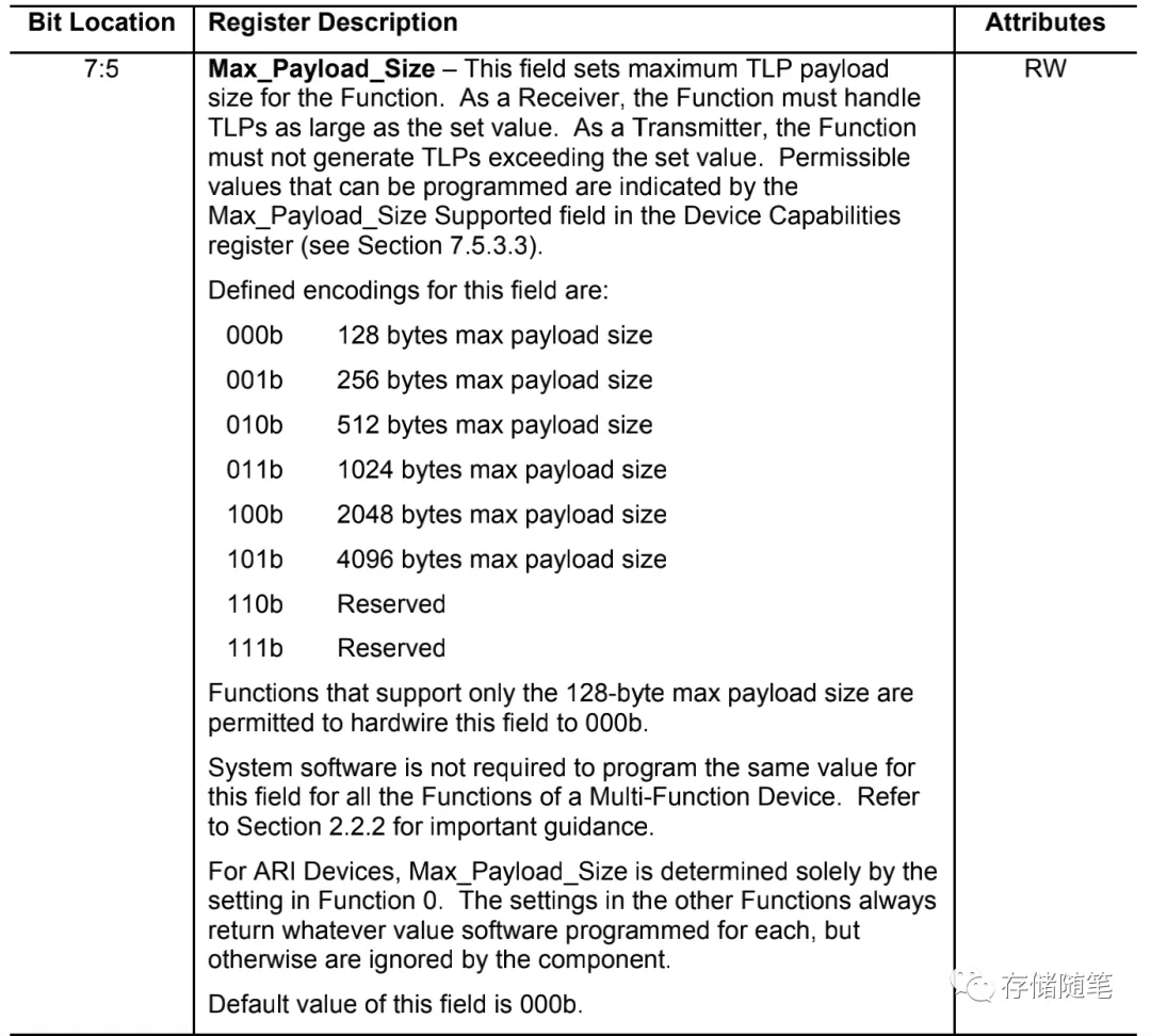
第一个: Max Payload Size, 简称MPS。这参数决定了TLP传输过程中大小。在接收端,需要使用同样的MPS大小,在发送端不能超过MPS的设置。在协议中可以设定128B-4KB,其中默认是128B。在Device Capabilities寄存器中可以查询MPS的大小。
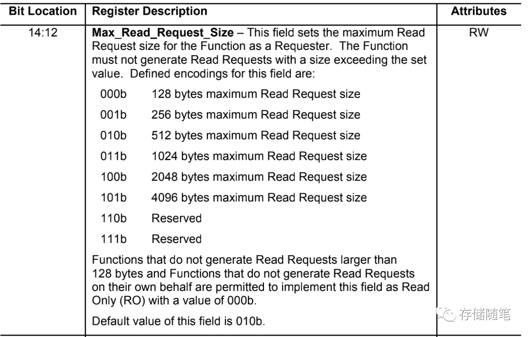
第二个:Max Read Request Size,简称MRRS。MRRS代表最大读数据请求大小,对于MRRS选择,同样有6种:128B,256B,512B,1024B,2048B,4096B. 这个参数也是在Configuration阶段,写入到设备的control寄存器。MRRS可以比MPS大,比如MPS设置为256B,MRRS设置为4KB,通常MRRS大于等于MPS。
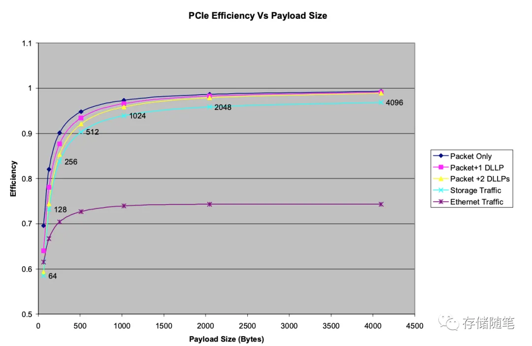
在MPS在PCIe整体性能中,有至关重要的作用。随着MPS大小的增加,PCIe传输效率也在不断提升。不过,在x86的机器中,RC端的MPS通常是128B/256B。在ARM CPU中,为了追求高效性能,部分场景也会设置为512B。
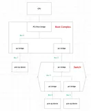
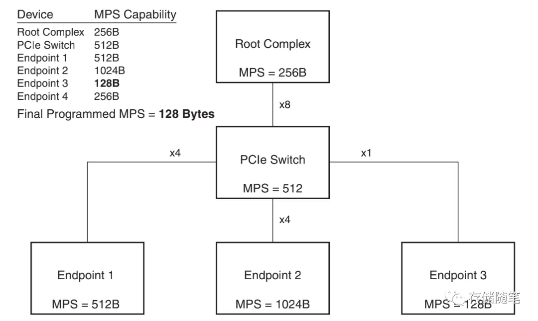
在整个PCIe系统中,MPS的大小,跟RC、PCIe Switch、Endpoint都有相互的影响,最终TLP传输的数据大小取决于MPS最小的一个设备。比如下图示例,RC MPS=256B,PCIe Switch MPS=512B,但是EP3 MPS=128B。所以最终数据传输的大小采用的是MPS=128B。
除了MPS影响系统性能,还有一个更加重要的事情,MPS对PCIe系统稳定性也起着决定性的作用。最常见的是,在系统中我们会看到pcie设备出现识别异常的情况,多数情况会看到一个“ Malformed TLP”,比如linux系统中的报错信息:
[ +0.002792] pcieport 0000:00:01.0: AER: Uncorrected (Fatal) error received: id=0020
[ +0.007830] pcieport 0000:00:01.0: PCIe Bus Error: severity=Uncorrected (Fatal), type=Transaction Layer, id=0008(Receiver ID)
[ +0.011387] pcieport 0000:00:01.0: device [10de:10e5] error status/mask=00040000/00000000
[ +0.008415] pcieport 0000:00:01.0: [18] Malformed TLP (First)
[ +0.006851] pcieport 0000:00:01.0: TLP Header: 20000080 010001ff 00000000 80004430
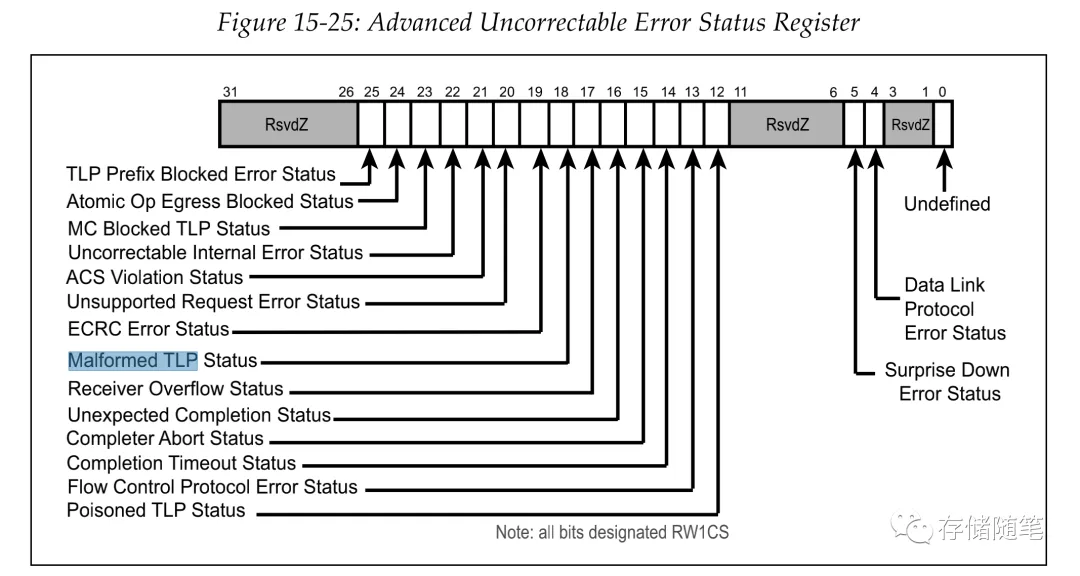
在PCIe spec中的Error Status Register的定义如下图:
上面linux报错信息中的error status=0x00040000,也即对应Error Status Register中的bit18被置位。
Linux系统中通过lspci和setpci可以查询和修改MPS/MRRS参数。
比如:lspci查看设备DevCap寄存器中MPS=512B,最终传输用的MPS=256B,MRRS=4KB。
lspci -s 04:00.0 -vvv | grep DevCtl: -C 2
DevCap: MaxPayload 512 bytes, PhantFunc 0, Latency L0s unlimited, L1 unlimited
ExtTag+ AttnBtn- AttnInd- PwrInd- RBE+ FLReset+
DevCtl: Report errors: Correctable- Non-Fatal+ Fatal+ Unsupported-
RlxdOrd+ ExtTag+ PhantFunc- AuxPwr- NoSnoop+ FLReset-
MaxPayload 256 bytes, MaxReadReq 4096 bytes
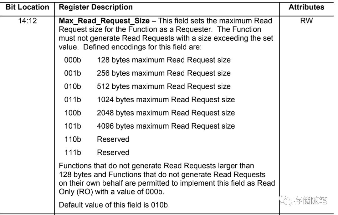
如果需要修改MPS或者MRRS,需要先找到Device Control Register中MPS和MRRS的位置,如PCIe Spec定义,MPS在bit5-7,MRRS在bit12-14. 同时Device Control Register的offset是0x8h。
比如小编环境中,PCIe Capacity的位置在0x70. 结合Device Control Register的offset是0x8h,我们就可以整体看到MPS和MRRS修改的PCIe配置空间的位置是在0x78h。注意,这个不同的机器和pcie设备中,PCIe Capacity的位置可能有所不同,有些在0x70,也有在0x60的,这个在修改参数的数据一定要关注下自己机器的位置。
用setpci修改MRRS:下面修改的命令,预期结果:把Device Control Register中的bit12-bit14从原始的101b修改成了010b,也就是把MRRS从4KB修改成了512B。
# setpci -s 04:00.0 78.w
5936
#setpci -s 04:00.0 78.w=2936
这个时候用lspci查看确认,发现MRRS已经修改成了512B。符合预期,说明修改MRRS修改成功了。MPS的修改方式也跟MRRS修改方式类似,这里就不赘述了。
# lspci -s 04:00.0 -vvv | grep MaxReadReq
MaxPayload 256 bytes, MaxReadReq512bytes
此外,在Windows如果需要修改pci配置空间信息,也可以安装windows版本的pci工具,使用方式类似,这里就不展开了。感兴趣的同学可以自行尝试哈!
在linux内核中,MPS/MRRS这两个参数,同样会受到内核pcie_bus_config_types的影响。以linux 5.19内核源码为例,pcie_bus_config_types定义有5种:
- PCIE_BUS_TUNE_OFF:不对MPS做任何操作
- PCIE_BUS_DEFAULT:保证pcie设备可以满足upstream的要求。
- PCIE_BUS_SAFE:将MPS设置为设备最大支持的值,这里也要参考水桶原理,最终采用最小MPS的EP设置。
- PCIE_BUS_PERFORMANCE:将EP pcie设备的MPS设置为RC允许的最大值,同时MRRS也设置为最大值。
- PCIE_BUS_PEER2PEER:相对比较简单,就是一个标准,把所有的RC/Pcie switch/EP的MPS都设置为128B,不偏不倚。
enum pcie_bus_config_types {
PCIE_BUS_TUNE_OFF, /* Don't touch MPS at all */
PCIE_BUS_DEFAULT, /* Ensure MPS matches upstream bridge */
PCIE_BUS_SAFE, /* Use largest MPS boot-time devices support */
PCIE_BUS_PERFORMANCE, /* Use MPS and MRRS for best performance */
PCIE_BUS_PEER2PEER, /* Set MPS = 128 for all devices */
};
extern enum pcie_bus_config_types pcie_bus_config;
在linux中通过pcie_bus_configure_settings执行配置。在性能调优过程中,一般会选择在linux启动命令行中添加命令行参数pci=PCIE_BUS_PERFORMANCE。如果没有配置的话,会选择默认设置PCIE_BUS_TUNE_OFF。
/*
* pcie_bus_configure_settings() requires that pci_walk_bus work in a top-down,
* parents then children fashion. If this changes, then this code will not
* work as designed.
*/
void pcie_bus_configure_settings(struct pci_bus *bus)
{
u8 smpss = 0;
if (!bus->self)
return;
if (!pci_is_pcie(bus->self))
return;
/*
* FIXME - Peer to peer DMA is possible, though the endpoint would need
* to be aware of the MPS of the destination. To work around this,
* simply force the MPS of the entire system to the smallest possible.
*/
if (pcie_bus_config == PCIE_BUS_PEER2PEER)
smpss = 0;
if (pcie_bus_config == PCIE_BUS_SAFE) {
smpss = bus->self->pcie_mpss;
pcie_find_smpss(bus->self, &smpss);
pci_walk_bus(bus, pcie_find_smpss, &smpss);
}
pcie_bus_configure_set(bus->self, &smpss);
pci_walk_bus(bus, pcie_bus_configure_set, &smpss);
}
在调用pcie_bus_configure_set函数时,如果pcie_bus_config == PCIE_BUS_TUNE_OFF || pcie_bus_config == PCIE_BUS_DEFAULT,函数会直接返回return 0; 在其他模式下,会主动调用pcie_write_mps和pcie_write_mrrs修改MPS和MRRS。
static int pcie_bus_configure_set(struct pci_dev *dev, void *data)
{
int mps, orig_mps;
if (!pci_is_pcie(dev))
return 0;
if (pcie_bus_config == PCIE_BUS_TUNE_OFF ||
pcie_bus_config == PCIE_BUS_DEFAULT)
return 0;
mps = 128 << *(u8 *)data;
orig_mps = pcie_get_mps(dev);
pcie_write_mps(dev, mps);
pcie_write_mrrs(dev);
pci_info(dev, "Max Payload Size set to %4d/%4d (was %4d), Max Read Rq %4d\n",
pcie_get_mps(dev), 128 << dev->pcie_mpss,
orig_mps, pcie_get_readrq(dev));
return 0;
}
通过pcie_write_mps函数修改MPS参数大小,这个函数只有在PCIE_BUS_PERFORMANCE模式下才会修改,其他模式就会直接使用默认MPS设置。
static void pcie_write_mps(struct pci_dev *dev, int mps)
{
int rc;
if (pcie_bus_config == PCIE_BUS_PERFORMANCE) {
mps = 128 << dev->pcie_mpss;
if (pci_pcie_type(dev) != PCI_EXP_TYPE_ROOT_PORT &&
dev->bus->self)
/*
* For "Performance", the assumption is made that
* downstream communication will never be larger than
* the MRRS. So, the MPS only needs to be configured
* for the upstream communication. This being the case,
* walk from the top down and set the MPS of the child
* to that of the parent bus.
*
* Configure the device MPS with the smaller of the
* device MPSS or the bridge MPS (which is assumed to be
* properly configured at this point to the largest
* allowable MPS based on its parent bus).
*/
mps = min(mps, pcie_get_mps(dev->bus->self));
}
rc = pcie_set_mps(dev, mps);
if (rc)
pci_err(dev, "Failed attempting to set the MPS\n");
}
通过pcie_write_mrrs函数修改MRRS参数大小,这个函数只有在PCIE_BUS_PERFORMANCE模式下才会生效,其他模式就会直接return返回。
static void pcie_write_mrrs(struct pci_dev *dev)
{
int rc, mrrs;
/*
* In the "safe" case, do not configure the MRRS. There appear to be
* issues with setting MRRS to 0 on a number of devices.
*/
if (pcie_bus_config != PCIE_BUS_PERFORMANCE)
return;
/*
* For max performance, the MRRS must be set to the largest supported
* value. However, it cannot be configured larger than the MPS the
* device or the bus can support. This should already be properly
* configured by a prior call to pcie_write_mps().
*/
mrrs = pcie_get_mps(dev);
/*
* MRRS is a R/W register. Invalid values can be written, but a
* subsequent read will verify if the value is acceptable or not.
* If the MRRS value provided is not acceptable (e.g., too large),
* shrink the value until it is acceptable to the HW.
*/
while (mrrs != pcie_get_readrq(dev) && mrrs >= 128) {
rc = pcie_set_readrq(dev, mrrs);
if (!rc)
break;
pci_warn(dev, "Failed attempting to set the MRRS\n");
mrrs /= 2;
}
if (mrrs < 128)
pci_err(dev, "MRRS was unable to be configured with a safe value. If problems are experienced, try running with pci=pcie_bus_safe\n");
}
此外,还可以在驱动里面单独通过pcie_set_readrq 函数调整MRRS参数,以达到提升性能的目的。
int pcie_set_readrq(struct pci_dev *dev, int rq)
{
u16 v;
int ret;
if (rq < 128 || rq > 4096 || !is_power_of_2(rq))
return -EINVAL;
/*
* If using the "performance" PCIe config, we clamp the read rq
* size to the max packet size to keep the host bridge from
* generating requests larger than we can cope with.
*/
if (pcie_bus_config == PCIE_BUS_PERFORMANCE) {
int mps = pcie_get_mps(dev);
if (mps < rq)
rq = mps;
}
v = (ffs(rq) - 8) << 12;
ret = pcie_capability_clear_and_set_word(dev, PCI_EXP_DEVCTL,
PCI_EXP_DEVCTL_READRQ, v);
return pcibios_err_to_errno(ret);
}
EXPORT_SYMBOL(pcie_set_readrq);